|
|
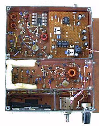
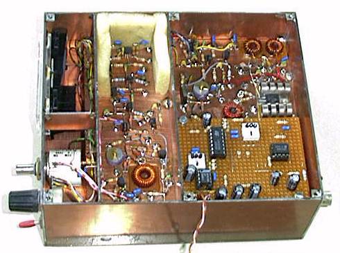
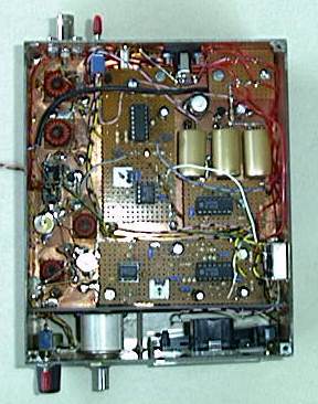
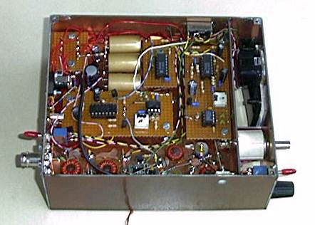
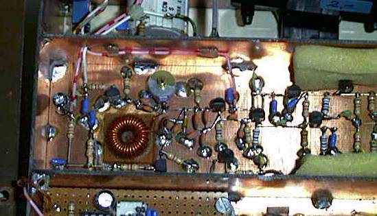
A complete circuit description and the schematic can
be found a bit further down the page. Here are a few pictures of the inside
of the TRX:
This was one of my very first
transceiver developments. This page was also one of the very first circuit
descriptions that I put on the internet quite some years agon. Today I would not
build a transceiver like I did then, but it was working, so I have kept this
page for historical (and sentimental) reasons. If you are a beginner in building
you own transceivers you might be able to steal a few of my ideas. Please let me
know if you do a full copy of the design, I would be interested in you practical
experiences when operation on the air.
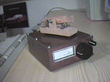
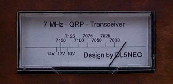
For a trip to the USA in June 1997 I have developed this little 40 meters transceiver. The receiver is a direct conversion receiver with a very good audio filtering. It is a real pleasure to listen to CW-signals, strong or week. (For SSB the filters are simply to narrow.) There is no AGC, just a manual gain control, but normally this is absolutely appropriate. Despite the absence of a preamplifier, the receiver is very sensitive due to the low noise figure of the NE612 doubly balanced mixer I used.
You may notice that I did not match the 1.5kOhm impedance of the NE612 to the 50Ohm antenna impedance. I had tried that, but it did not do any good. There are still very strong AM broadcast stations in eastern Europe only a few kHz above 7.1 MHz. If you match the antenna to the mixer, these signals are so strong that they are demodulated and you can hear their program independent on the frequency you are tuned to. This may not be a problem in the US, but is certainly is here in Europe. I have even added a potentiometer just in case that there should be a broadcast station that is still too strong.
The transmitter is very simple. The local oscillator is shifted about 700Hz and is then amplified up to a little more than 1.5 Watts. The 2SC2166 transistor is made for up to 5 watts at 30 MHz, so it would be no problem to get 5 watts on 7 MHz. I chose not to match the transistor to 50 Ohm to reduce the power to 1.5 watts in order to save battery power. (I intent to run it with 8 AA battery cells). I have already had a couple of contacts to a number of countries here in Europe with the transceiver and I can guarantee that 1.5 watt is enough and that live is not to short for QRP. (In this circuit the transistor won't be damaged even if you key the transmitter without any antenna. Believe me, I tried it). The transistor is probably able to survive a 100% duty cycle without any heat sink. I used a small aluminum heat sink of one-by-one inch. It warms up just slightly. The efficiency is about 70% in my circuit.
Now have a look at the circuit diagram. After that I will give you some advices in how to rebuild it.
As you saw already in the circuit diagram, almost all the amplification is made on the audio frequencies. (The NE612 has a mixing gain of about 15-18dB). This means that you have to be very careful with the supply voltage to avoid oscillation. All points in the circuit that are marked +12V are directly connected to the battery pack. All other voltages should be created with small fixed voltage regulators (the 100mA-types, for example the 78L05 or the 78L09). Use a separate regulator for each part of the circuit. (Please feel free to add as many electrolytic capacitors to the supply voltage as you may find appropriate. After all: it is your circuit)
For tuning I used a helix-potentiometer with 10 turns so that I have 15kHz per revolution. I added the 2k resistor so that the tuning voltages is between 1.5 and 5 volts. This keeps the phase noise low and it helps to reduce the frequency drift. In RX-mode the LO is by far good enough. Probably you won't even notice any drift at all. In long TX periods the TRX starts to warm up a bit which causes a significant LO drift. If you can life with that - fine. I decided I would like to have a perfectly stable LO and have therefore exchanged the analog LO by a PLL synthesizer. Read more about that in "A face-lift for the 7MHz TRX".
The current consumption is between 45 and 100mA (depending on the loudness of the received signal in the speaker). When transmitting the consumption is a little less than 400mA.
By the way, the key that can be seen in the photo is also homemade. It works quite well with this TRX as well as with my Kenwood 2m all mode TRX.