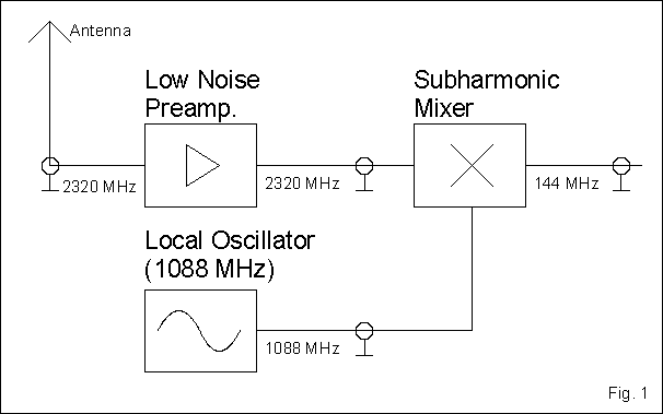
The receiving converter consists of three modules. The preamplifier, the local oscillator (1088MHz) and the subharmonic mixer itself. (Fig. 1)

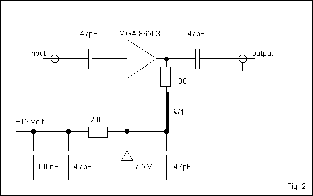
The preamplifier is very simple. I used a Low Noise integrated circuit manufactured by Hewlett Packard. The device name is MGA86563. It has a Noise Figure of about 2dB and can be used from 0.5 GHz to at least 6 GHz. The gain is about 20-22dB at 2.3 GHz. The input and output ports are internally matched to 50 Ohms. All you have to do is to put a capacitor in front of the device and behind it and provide the necessary supply voltage of 5-7 Volts at the output port. I used a quarterwave stripline for the supply voltage. The 100 Ohms resistor is used to "de-Q" the circuit in order to avoid oscillations.This resistor causes a voltage drop that must be equalized by a somewhat higher supply voltage of 7.5 Volts.(Fig. 2)

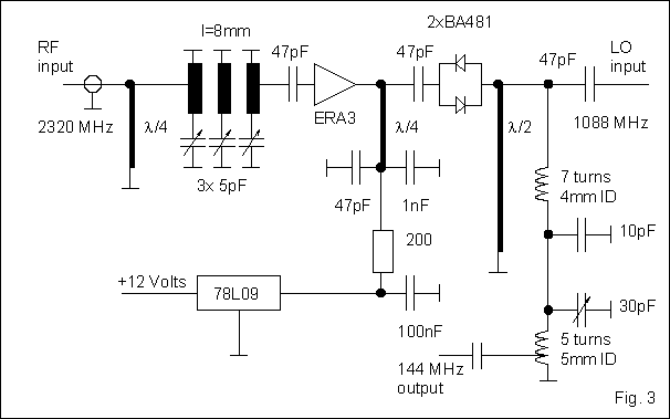
The harmonic mixer is not much more than two Schottky Diodes BA481. They short circuit the signal twice at every periode of the LO signal (at every half-wave). At the input there is a bandpass filter to suppress the image frequency. A monolitic amplifier ERA 3 from Mini Circuits (New York) amplifies the signal for another 20dB. This is not necessary in order to have an optimal sensitivity (the preamp would be sufficient without another amplifier) but it helps to have a strong signal at 144 MHz. This allows you to put the converter at the antenna and use a cheap coax cable for the IF. A 144 MHz amplifier at the output is not advisible because strong 144MHz-signals from the neighborhood could get into the amplifier and then cause interference to your 13cm signal. The LC-transformation-circuit at the output makes sure that the mixer is not overloaded by the 50 Ohms of the IF receiver. (Fig. 3)

I will not give the circuit diagram for the 1088 MHz local oscillator. It is really not adviceable the way I did it (now I know!). I built a 1088 MHz VCO and phase-locked it using a MC74HC4046 phase comparator and a U893 prescaler. As a reverence oscillator I needed a 17 MHz oscillator but I could not get a 17 MHz crystal. So I used a 12 MHz crystal oscillator and mixed the signal using a NE612 with an adapted 5 MHz crystal. After filtering the 17 MHz-signal I was able to feed it into the 74HC4046 phase comparator. The circuit works good so far, but the sideband noise of the oscillator signal is not half as good as that of a multiplied crystal signal. Despite the fact that I used a high cut-off frequency for the PLL low pass filter the oscillator signal is still a little bit noisy. So I suggest that you use one of the many circuits that are available for 23cm converters. They produce a LO signal of 1152 MHz by multiplying a 96 MHz crystal oscillator by 12. If you use a 90.667 MHz crystal you get 1088 MHz. An output of 5mW will be very fine but 2mW will also work well. (You don't have to have a lot of harmonics in your signal because there are two diodes in the mixer. I would work well even if your LO signal would be 100% clean.)
The converter works just fine here at my station. We have compared the sensitivity to that of comercially built converters and were not able to detect any difference. If I use SSB I do not notice the LO sideband noise. (That is why several amateurs use this kind of LO for satellite reception at 13cm.) When listening to FM signals from my friends in the neighborhood the audio signal is always a little bit noisy even if the signals are strong enough.