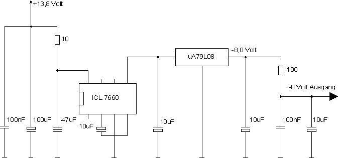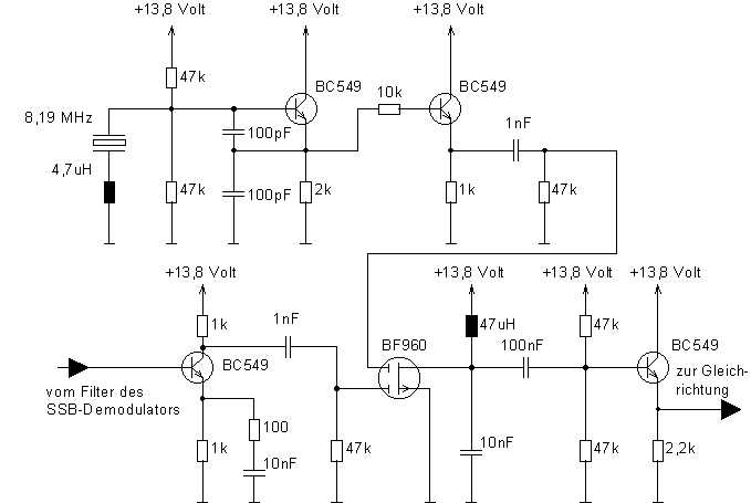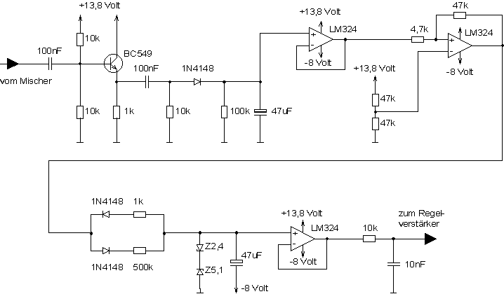

Because of the high gain which we already have on 8 MHz it is not easy to amplify the IF signal to a degree that is large enough for rectivication. Of course it is possible to use the AF signal to produce the AGC signal but since the AF frequency is quite low the AGC would not work very nice and fast. So I decided to use a quite unusual concept. I mixed the IF signal down to 190 kHz which is low enough for easy amplification and high enough for fast AGC performance.

Now we can go ahead and rectify the amplified 190 kHz signal. AGC operation is best if you have two time constants. When there is a very strong signal the AGC has to reduce the IF gain very fast. The AGC gain has to stay low for a few seconds before it increases again. This way you get a very nice audio output for every input signal. I have made this by using two diodes, one for charging the capacitor and one for discharging. Every diode is put in series with a resistor that determines the time constant.
