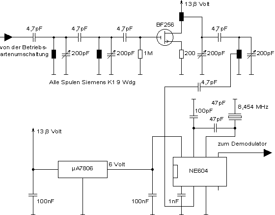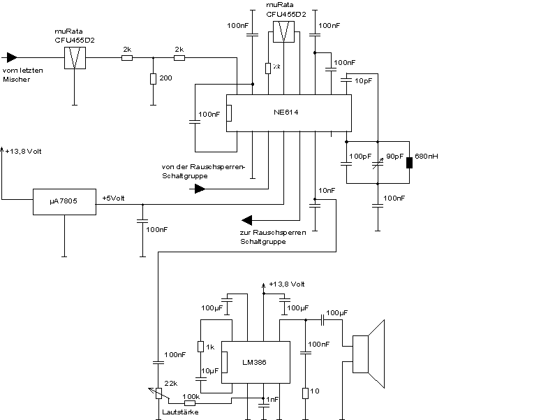

For the demodulation itself a integrated circuit NE614 is used. It features a high gain limiting amplifier, the demodulation circuit and a radio signal strengh indicator with a dynamic range of more than 80dB.

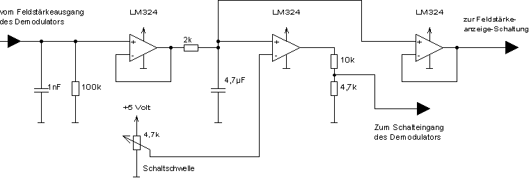
What's left to do now is to build a squelch circuit for the FM receiver. Since we already have a voltage that is proportional to the input signal strength this is the easy part. We just have to use a comparator to decide weather there is a input signal or not. The output signal of the comparator is feet back into the demodulator which has a digital mute input.
