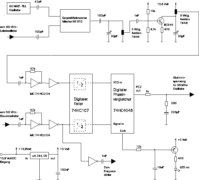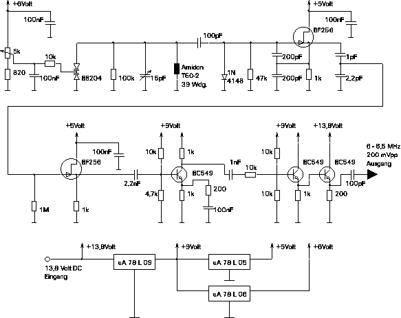
Lets start with the 6 MHz oscillator. The highest priority in this circuit is its long term frequency stability. You might be surprised about the many buffer stages. I tried to make sure that the output frequency is 100% independent of the circuit load (and it seems that I even overdid it a little bit).

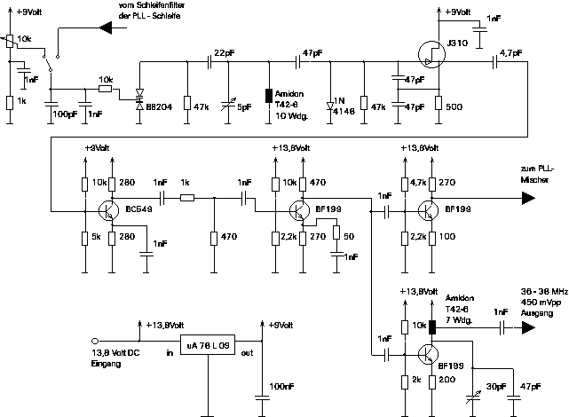
Now we will have a look at the 36 MHz oscillator. It turned out that the shunt diode increase the phase noise. Therefore I recommend to skip it. The 22pF coupling capacitor can be increased to 27pF which gives a bit more tuning range. All capacitors in the resonator (i.e. between the BB204 and the J310) should be "zero temperature drift" types. The trimming capacitor is a silver-air-trimmer, but the long term stability will not decrease a lot if you use a cheap trimmer since the influence of this capacitor is quite small.
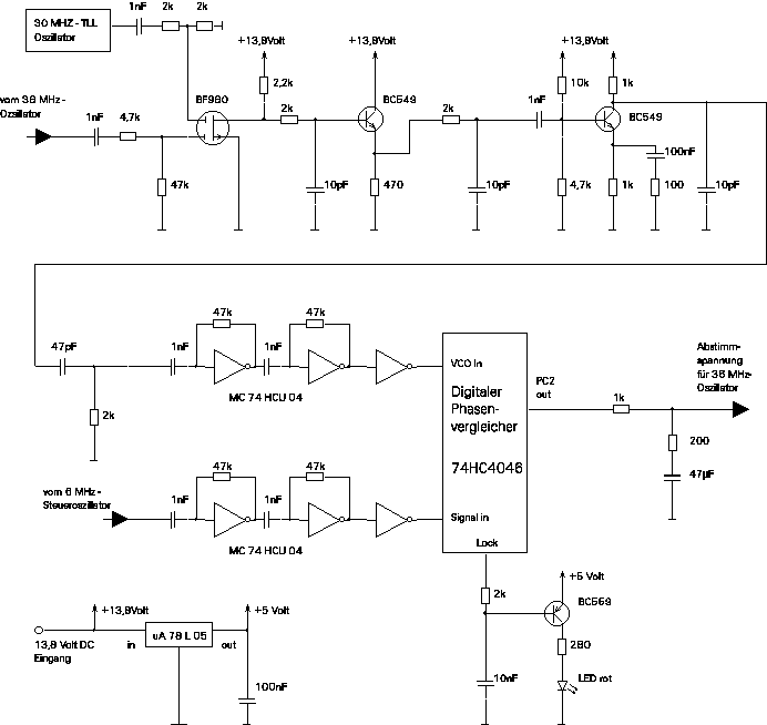
The 36 MHz oscillator above is phase locked to the 6 MHz Oscillator by the following circuit.
And finally here is the 96 MHz oscillator which we will feed into the mixer to convert the input signal to the first IF of 48 MHz.
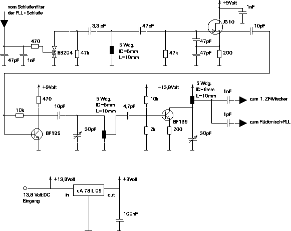
This is the PLL circuit that is used to phase lock the 96 MHz oscillator to the 36 MHz oscillator.
