The Digital Frequency Readout
Due to the local oscillator system with the 36 MHz control
oscillator it is easy to build a digital frequency readout for this receiver.
First we have to compare the RX frequency (which we would like to show
at the display) with the frequency of the local oscillator (which we could
count with a frequency counter). Lets have a look at a few exambles:
| RX frequency |
LO frequency |
| 144.000 |
96.000 |
| 144.550 |
96.550 |
| 145.800 |
97.800 |
| 146.050 |
98.050 |
We could mix a frequency of 48 MHz to the LO signal to get
the real RX frequency. Despite the fact that we would generate a very strong
interference signal for our receiver we would have to count a relatively
high frequency. Fortunatelly for us there is another possibility. Have
a look at this exambles:
| RX frequency |
36 MHz Oscillator |
| 144.000 |
36.000 |
| 144.550 |
36.550 |
| 145.800 |
37.800 |
| 146.050 |
38.050 |
Remember? The 36 MHz oscillator is always synchron to the
96 MHz local oscillator. This means that we can mix the 36 MHz oscillator
signal in a way to use it for the frequency readout. Since the RX frequency
always starts 14x.xxx we can put the numbers 1 and 4 in front of the variable
numbers. All we have to do to get these variable numbers is to substract
32 from the 36 MHz oscillator signal. (Have a look at the table above and
you will see that I am right.) One examble: 145.350 means that the 36 MHz
oscillator runs at 37.350 MHz. We substract 32 and get 5.350 MHz. We put
a 14 in front of the 5.350 and get 145.350. See, it works!
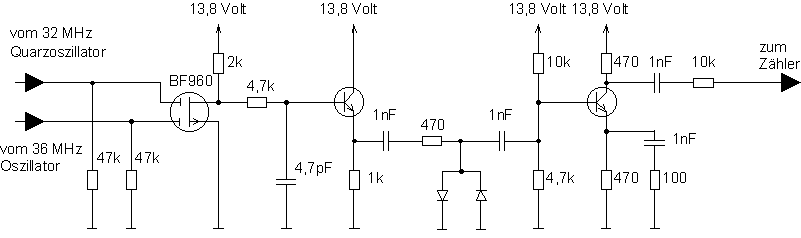
To substract 32 we simply have to mix the signal from
the 36 MHz oscillator with a 32 MHz crystal oscillator signal. And here
is the circuit to do this.
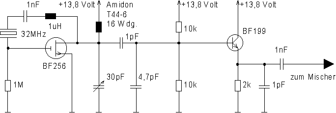
And this is the crystal oscillator which we use to generate
the 32 MHz signal.
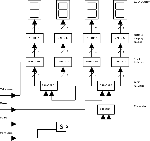
Now we have to count the signal which is located between
4 and 6 MHz. Since every modern digital gate is easily capeable of working
at 6 MHz this is the easy part. We just have to open a digital gate for
an exact amount of time (I choose 10ms), count the edges and put the result
to a memory which is connected to a LED display. Then we have to reset
the counter and start again. This means we have to have the following control
signals:
The accuracy of the counter can be only as good as the
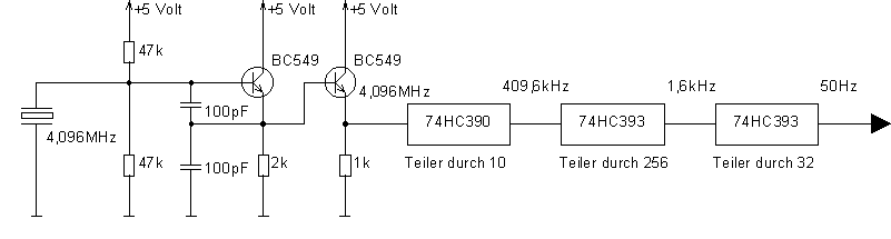
reverence frequency. This means we need a very exact 50 Hz reference frequeny.
I decided to build a 4.096 MHz crystal oscillator and divide the signal
down to 50 Hz.
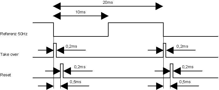
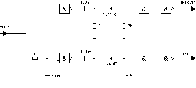
From the 50 Hz reference signal we can create the takeover
and reset signals with the following circuit.
Now we have all control signals we need to put the digital
counter together. And here is how to do it.