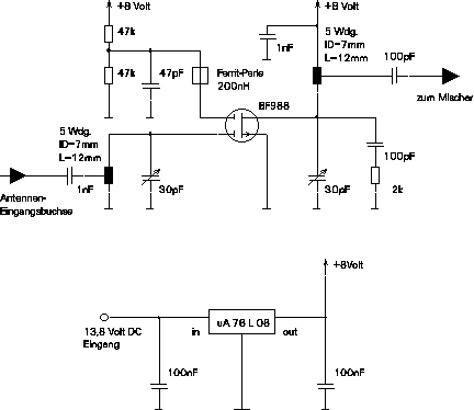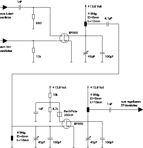

Now that the signal is amplified for about 20dB we can now mix it down to the first IF.

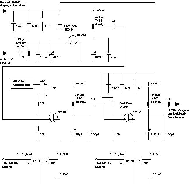
For SSB operation the RX has to have a variable gain IF amplifier in order to get a demodulator output voltage that is independent from the signal strength at the antenna. This circuit includes the second mixer down to the second IF. This means that one part of the gain variation is done at 48 MHz and the other part at 8 MHz. This makes is possible to get a dynamik range of over 100 dB. (The maximum gain is only about 50dB but the circuit is able to attenuate the input signal for another -50dB). For FM operation the gain is set to a fixed level with a potentiometer. For SSB it is connected to the AGC (automatic gain control) unit.

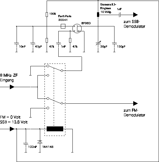
After the variable gain amplifier the signal is either switched to the SSB or the FM demodulator. Since the maximum amplification of the variable gain amplifier is a little bit to low for SSB there is another fixed gain amplifier located in the SSB line.
