|
|
RF Power Sensors
Sampling a RF signal directly in the time domain (i.e. viewing the signal with an oscilloscope) is usually limited to frequencies below 20-100MHz, depending on the bandwidth of the oscilloscope. There are oscilloscopes on the market with sampling rates of 20-50Gs/s and bandwidths up to 10-20GHz. Their prices however are located in the 6-digit Euro range, so only very few amateurs will be able to afford that luxury. If you would like to see a 2.3GHz beacon signal on a scope, click here for a picture that I have once taken on a 20Gs/s scope. The other device that can show RF power (not in the time domain but in the frequency domain) is a spectrum analyzer. When it comes to the price, a spectrum analyzer is also much too expensive for the poor radio amateur.
For us amateurs there is no other way than to convert the amplitude of the signal into an equivalent DC voltage. The DC voltage can than be measured with a standard ADC (analog-digital-converter) or a cheap multimeter. I know of three good ways how to do this, hence I have developed three different sensors for my powermeter. If you know another good way, please let me know.
All three ways of
converting RF power to an DC voltage have advantages and disadvantages.
So depending on your actual requirement, one or another sensor may be best
suited.
1. Thermal Sensor
In an thermo sensor the incoming RF signal is absorbed in a small dummy load. A standard 50 Ohms chip resistor (e.g. 0603) can be used up to 5-10GHz with very good results. Due to the power dissipation from the RF signal, the resistor warms up. The change in temperature can be used to determine the power of the RF signal. If we glue a NTC (a resistor that changes its resistance depending on its temperature) on the dummy load and include it in an measurement bridge, we get a voltage difference that is equivalent to the input power. A second NTC of the same kind in the bridge can be used, to eliminate the ambient temperature influence.
The nice thing about
this principle is that it is basically independent of the frequency of
the input signal. The resistor does not care if it is warmed up by a noble
10GHz beacon signal or by a cheap DC signal that can also be measured by
a standard multimeter. Therefore every amateur can calibrate his homemade thermal
sensor by applying different DC voltages to the input and writing
down the resulting bridge voltage. Whenever you see the same DC output
voltage as with a certain DC input level, you know that the power of your
measured signal is the same, independent on the frequency or waveform of
your signal.
2. Diode Sensor
In order to convert an AC-signal level (i.e. our RF signal) to an analog DC voltage that we can measure, we can simply use a diode. Of course we have to use a special RF diode that is fast enough, has very little capacitance and is housed in a very small package to keep the series inductance as small as possible.
There is a big prejudice on diodes stating that an diode only starts to conduct (hence to rectify) when the voltage is above the diode threshold voltage (0.3-0.7 Volts, depending on the technology of the diode). If this was true, we would indeed be in trouble if we tried to measure RF-signals in the mW range. (1mW on 50Ohms is only 223mV)
However, the diode is always an unlinear component, so even with the tiniest AC-signal, there is an DC output voltage. There is indeed a change in behavior around a few hundred mV, but it is just a soft transition from the so called square law region to the linear region.
In the square law region (roughly speaking below the threshold voltage) the diode already exhibits a different resistance in forward and backward direction. The difference is not as distinct as above the threshold voltage, but it is still there. The result is a DC-voltage that is proportional to the power of the signal, i.e. it is proportional to the square root of the peak voltage of the signal.
In the linear region the diode simply conducts at the positive half wave and isolates at the negative half wave. That is exactly the behavior that we all know from large signal rectifiers like in power supplies etc. The result is an DC voltage that is directly proportional to the peak value of the input signal, therefore the name linear region.
There
is a very good application note (ANP1014) on
diode sensors from Alpha Industries. It is their zero-bias schottky detector
diode SMS 7630 that I have used for my best diode sensors. The easy-to-get
BAT62 also gives a very flat frequency response, but the video resistance
is higher. If we use a high-impedance multimeter or ADC to measure the
DC output voltage, that does not really matter.
3. Logarithmic Amplifier Sensor
A logarithmic amplifier is essentially a converter from an AC amplitude to a DC level. The very nice thing about them, is the fact that the DC voltage is proportional to the logarithm of the input level. In other words, the DC level is proportional to the input level measured in dB. For every dB the input amplitude raises, the DC output raises for some millivolts. Therefore we can measure over a very wide dynamic range (from very small input signals to rather big ones) without the need for a high amplification of the DC voltage. Even with amateur means we can measure over at lease 50-60dB dynamic range (i.e. signal power factors of 1 million from the smallest to the largest signal that we can measure).
The disadvantage is that the precision is not very high, especially when we measure at different frequencies. Like every amplifier, the log amp changes its behavior over frequencies. Of course the manufacturers of integrated log amps try to eliminate this effect as much as possible.
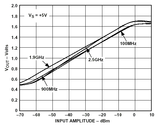
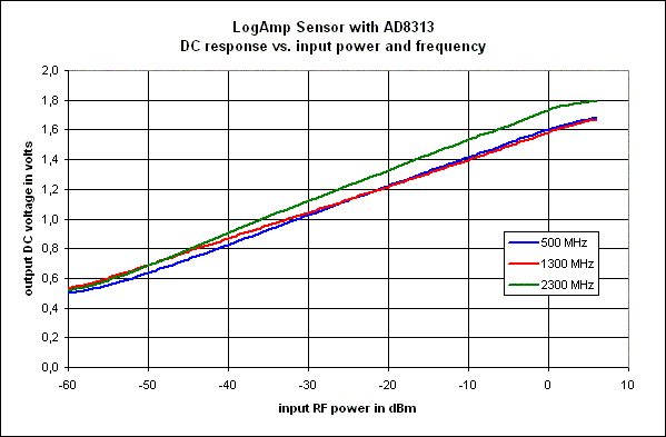
For some time now there are very nice integrated log amps available on the market. For frequencies up to 2.5GHz the AD8313 from Analog Devices is the only one I know of. That is the one I have used for my logamp sensor. The external component count is very low and unless you use components that don’t work to 2.5GHz the results should be very repeatable. I.e. if you copy my log amp sensor with similar components, you should be able to use the lookup table in my software without modification with good very results. This is the chart from the datasheet, and this is the results that I got in my complete sensor. As you can see, both compare very well, so I have not wasted any significant precision in my circuit.
A
very good and extensive article on logamp theory can be found on pages
7 to 10 in the datasheet of the AD8307 logamp
sensor. I doubt that I could add a lot to this very professional paper
from the specialists at Analog Devices, therefore I won’t even try.
Pros
and cons on the different sensor types:
| Sensor Type | Advantages | Disadvantages |
| Thermo Sensor | can be calibrated with DC, almost no variation over frequency, can be homemade up to 10GHz, high accuracy, always shows the true RMS value of the input signal | low dynamic range, slow sensor response |
| Diode Sensor | good accuracy over a reasonable dynamic range, good compromise for all kind of applications | signals with a lots of harmonics, (i.e. none sinusoidal signals) can lead to inaccurate power readings |
| Log Amp Sensor | high dynamic range | high variation over frequency, needs frequency correction for reasonable accuracy |